
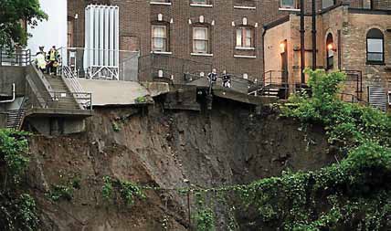
MASS FAILURE is perhaps the most ubiquitous geohazard. Typically, when one imagines what a landslide looks like, images of mudslides from mountainous regions like California come to mind. These are, after all, what make the national news cycle. Unfortunately, slope failure impacts a wide range of landscapes, even those considered relatively level. For example, the Twin Cities Metro is experiencing an increasing number of slope failures that significantly impact infrastructure and property. Often, these failures are a result of significant rainfall events; the 2014 slope failure along West River Parkway in Minneapolis is an example of this phenomena. This slope failed after over 11 inches of rain fell in two days, impacting a popular recreational trail as well as a major health care facility. Repairs cost close to six million dollars.
Clearly, slope failure is a geohazard that impacts many types of infrastructure, from individual homes, to municipal storm sewer networks, to oil and gas pipelines. In fact, the Pipeline and Hazardous Materials Safety Administration (PHMSA) requires that natural gas and hazardous liquids pipelines develop risk assessment programs for slope failures in their systems. Likewise, many municipalities are beginning to incorporate these types of risk assessment programs into their own planning activities.
So, what causes slope failures? Like all geohazards, the causes are myriad and complex. Establishing a framework of how the physical processes behind slope instability function is crucial in determining risk.
Slope stability is based on the interaction of two forces: driving forces and resisting forces. Driving forces promote the downslope movement of slope material; resisting forces resist movement. Slope failures occur when driving forces overcome resisting forces. Typically, the driving force is gravity and the resisting force is the slope material’s shear strength. Shear strength is basically the ability of the slope material to hold the slope in place.
When assessing a slope’s stability, indications that physical processes are decreasing shear strength is a sign that a slope is nearing failure. These indications can include:

- Weathered geology: Weak, weathered bedrock, jointed bedrock and bedrock that dips parallel to the slope can decrease stability.
- Vegetation removal: Droughts, wildfires, and humans can remove vegetation from the slope, decreasing stability.
- Freeze/thaw cycles: Water in rock joints or in soils can act to decrease slope stability.
- Stream action: Rivers can erode the bottom of the slope (called the toe), decreasing stability. This can occur over time through normal stream action or catastrophically during flood events.
- Human modifications: Humans modify stability through many actions, such as excavation of the slope or its toe, loading of the slope or its crest, surface or groundwater manipulation, irrigation, and mining.
- Slope angle: Generally, steeper slopes have greater risk for instability.
- Soil type: Soils have variable amounts of shear strength, dependent on many factors like soil texture, pore water, and particle cohesion.
- Water sources: Water works in many ways to reduce shear strength. For example, pore water pressure in soils decreases shear strength; saturated soils are more likely to lead to slope failure. Perched water tables, groundwater seeps, and excessive precipitation are some examples of water sources that may lead to slope failure in certain conditions.
Because many factors influence slope stability, a full analysis of a slope should be considered when determining the risk of mass failure.
After the geomorphic factors for each slope crossing have been assessed, we can determine the likelihood of slope failure at particular locations. Then, we can multiply that probability by the consequences of failure to derive a risk factor.
An example of a risk matrix developed for slope stability is presented on the previous page. In this matrix, the likelihood that a slope failure will occur is multiplied by a known consequence to derive a risk factor (from the formula). In order for this type of risk matrix to work, robust rational and consequence definitions should be developed to support the risk estimation. In this example, geomorphic analyses have resulted in a specific set of justifications for the likelihood of slope instability. These categories are then assigned risk factors.
Likewise, detailed definitions have been determined for the Failure at Road consequence, and those definitions have been assigned risk factors. For example, slope failure at a road is considered Critical (5) if the road is a critical evacuation route, major transportation corridor, or restricts access to emergency facilities. Almost Certain (5) slope failures at Critical (5) roads have a Risk Factor of 25 and require mitigation.
While this example matrix only lists one consequence category (Failure at Road), you can design your risks matrix to include as many consequences as necessary to capture the complete risk profile for your needs. Additionally, the application of 5 risk factors is merely an example. Risk matrices can be designed with as many or as few risk factor categories as necessary.

The outcome of this analysis is a set of risk factors that pipeline operators, city planners, engineers, or transportation officials can use to prioritize capital spending in a non-biased way, proactively estimate capital budget, manage interim risks, and more accurately estimate maintenance budgets.
Jen Holmstadt is Director of Oil/Gas Services with WSB and Associates. She has 10 years of experience as an environmental consultant, specializing in geohazard risk assessments, contaminated site remediation, and project management. She can be reached at jholmstadt@wsbeng.com.
![ESM Sidebar Ad[87]](https://excavationsafetyalliance.com/hubfs/ESM%20Sidebar%20Ad%5B87%5D.gif "ESM Sidebar Ad[87]")


Comments